 AWT–1856
AWT–1856
AWT–1856
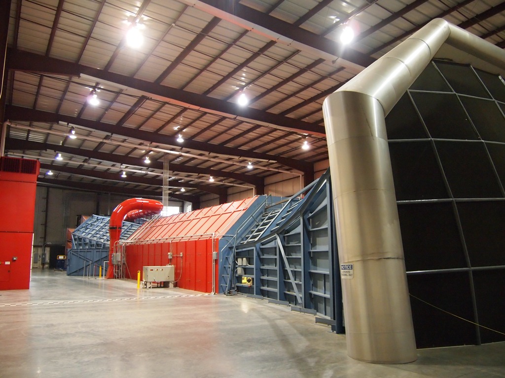
Full-Scale Closed-Jet Contoured-Wall Facility
with Moving-Ground Simulation
As an independent wind tunnel, we serve all brands of cars. Our first and only priority is to provide you with an accurate, repeatable, and productive facility. Our focus is strictly limited to testing. By avoiding any vehicle-related consultation, our customers will be assured complete confidentiality.
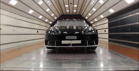
The AeroDyn Wind Tunnel is a full-scale, closed-jet, contoured-wall facility employing a revolutionary moving-ground simulation. The test section measures approximately 185 ft² and operates at speeds to 130 MPH.
Unlike other tunnels, the facility features 22 individual 100HP fans. This allows for rapid start up and shut down. Active fan braking slows the array after a run, allowing a fast turn around.
| Parameter | Value |
|---|---|
| Test section area | 185 ft² |
| Maximum test speed | 130 MPH |
| Fan array | 22 × 100 HP |
| Wheelbase accepted | 104.5″ – 123″ |
| Track accepted | 55″ – 65″ |
| Front axle weight | 4,000 lbs |
| Rear axle weight | 2,000 lbs |
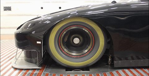
To complete our simulation of a moving ground plane, we are able to rotate the wheels to match the wind speed. This, coupled with our boundary layer control, allows us to simulate what the car experiences while on the track.
Unlike most wind tunnels, AeroDyn yaws the vehicle about the front axle, similar to what is seen on track. Our tunnel is able to yaw the vehicle from +3° to −5°. This automation allows for quick aero-mapping with precise, repeatable results.
Our in-house designed Ride Height Control System (RHCS) revolutionized the way we do testing. This is the 3rd generation of our RHCS, allowing precise movements to 0.001″. Complex ride height maps are loaded via a simple Excel spreadsheet, with manual fine tuning available to the customer in the tunnel.
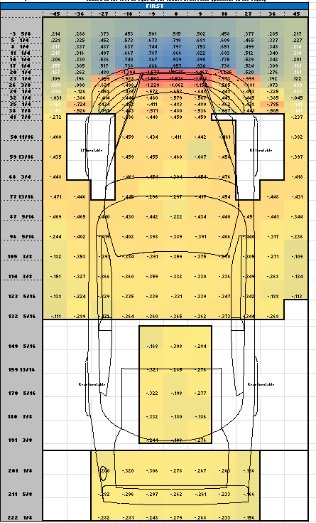
Because of our unique boundary layer control solution, we are able to provide customers with unprecedented instrumentation of the underbody. Beneath the car, integrated into our floor, we have a grid of 264 static pressures. In addition, we can interface with up to 62 customer supplied vehicle pressure taps.
AeroDyn offers a number of add-on systems that customers can use as part of their testing. These systems are provided at no added cost to the customer.
| Designation | System | Capacity |
|---|---|---|
| HDPS | High Density Pressure System | 124 sensors |
| ICADS | In Car Analog Data System | 20 channels |
| HARPS | High Amperage Remote Power Supply | iPad control |
| — | Duct anemometers | (6) 3″ · (6) 3.5″ · (2) 4″ |
| — | Radiator anemometers | 3 configurations |
| — | Continuous motion / real-time acquisition | — |
| — | Customer DAQ trigger (Pi / Motec) | — |
| — | Smoke wand, macro flow visualization | — |